
DIY Portable Solar Power Bank
The 45Ah power bank works well after many uses and still does so but it is quite bulky and heavy. Also, having a separate PV module means it is a little cumbersome.I decided to make a slightly smaller version but using 18650 Li-ION cells from used laptop packs. Check out the build log below.These are the used cells. Each one had been fully charged and discharge tested for capacity and internal resistance using my Turnigy MAX80W.
The pack will be a 3S15P configuration totaling 11.1V 39Ah nominal.
I used aluminum angle clamped to the bench as a guide to position all the cells.
The cells are then hot glued to each other to make it mechanically stable.Almost done on the third stack.
Closeup of the gluing process.
I used the "Tesla" style individual fuse links on the interconnects for some protection.
The wire used is #30 wire wrap wire with the insulation stripped.
Copper tape is used to parallel the entire 15cell groups.Temporary wires for the balance taps are installed for the initial pack charge and balancing.
It took a while but it finished without problems.
Time to add the balance plug.
To add strenght, hot glue is added as strain relief.And then heatshrink tubing is used for more strain relief. This makes gripping the plug easier.
The main power connections used gold plated 3.5mm bullet plugs.
The pack is also shrinkwrapped with clear tubing.The completed pack.
A 10W PV module is planned for this application.
It won't run a bunch of appliances but should be enough for basic loads and is small enough to be portable.The frame is made from aluminum C channel about 2 inches wide.
One chamber holds the battery pack and electronics while the other is an open area to place cables and accessories or other stuff in.Battery gauge will use this small PCB but it only works for single cell 3.7V packs.
Some clever switching will be used to allow using it for the 3S pack.With the LEDs lit.
Discharge testing to see how well the packs hold up under load.
I used the MAX80W to dump the energy into the home off-grid RE system rather than just burning it off the electronic load.
The cells worked well enough with about 20mV max differences in voltages.
I was only able to get about 15Ah due to the MAX80W input cutoff voltage set too high.Cutting the end panel for the battery gauge.
Battery gauge and knob on this side.
The knob is for selecting which parallel group's voltage to display.
It will also serve as a power switch for the outputs.With the gauge lit for testing.
Drilling the other end for the output connectors.
Output connectors.
Two USB ports max 3A total, two barrel connectors and a pair of 4mm banana jacks.On the inside rail, The PV input is through this binding post.
This would allow me to splice in a bigger PV module if necessary.
Placing this connector inside also allows me to leave the PV module connected even when closed to allow charging even while traveling.The USB ports are powered from this brick converter.
For completeness sake, a car cigarette lighter socket is added on the inside incase I wanted to use a small car inverter.
It is starting to get pretty tight.
Cutting some acrylic sheets for the bottom cover.
I forgot to take pics but it is just a flat piece so you didn't miss much here.The inner panel is also made from acrylic with some polycarbonate legs to hold the battery pack in place.
It is simply held by four screws on one side and lifts out for access.
The battery pack is also supported by foam blocks to act as shock absorbers.A detail of the polycarbonate clamps.
It fits in the PV module frame to keep it on when closed.
The acrylic sheet then fits inside the frame.Unfortunately, the C channel has a smaller lip than the PV module so we end up with an open slot but it should not pose much of a problem in use. It can also act as ventilation slots.
This is where the PV module slides into.
Add two latches on top and it is almost done.
I still need to buy a handle for this.The back side is transparent but I plan to black out the lower part of it.
The latches and hardware I used are stainless steel since the PV module could be left out in the weather.
With the internal slide catch, we get a clean outside edge.
I was originally planning on getting a hinge that could be separated but they were too big. Good thing I was not able to find any.
More to come when the PCBs for the balancer circuit arrives and wiring commences.
25 Feb 2016More work.
A protective cover for teh battery gauge.The acrylic piece is marked where it will show through the case.
It is then milled to size.
A little small but useable.
Holes are partly drilled on the other side so the PCB can sit flat and the SMD LEDs shall reside in the holes.
And here it is.
The acrylic piece also serves to insulate the PCB from the metal case.
LED shines through just fine.
Now for the power electronics.
A blank PCB is marked and cut. The table saw is set very shallow to electrically separate the copper foils.The copper side is cleaned using a dremel.
Power fets and diode wired up. Two IRF3205s are wired in parallel to control the PV input. These are wired in parallel for thermal considerations rather then current handling as these will run in linear mode. The diode (18TQ045) is a blocking diode for the PV input. An IRF1305 is used for output switching.
Wired in for testing.
The PCBs arrived!
Here is a simple balancer module. Just use one per parallel cell bank so I would need three since this is a 3S pack.
I populated six for spares.
The three are snapped off, wired in series then tested.
Each cell is set to 4.15V max to prolong its cycle life as when full, it will be kept charging via the PV until the sun goes down. This balancer circuit is the dumb kind each are based on a TL431 somewhat similar to the balancer in the discrete charger somewhere in this site.
There is not much space in the battery compartment so I had to mount it in the other chamber.
The outputs are als wired in.
Used my bench supply in CC mode to charge the pack until the balancers kick in.
I also added a stainless steel handle.
It is mounted using blocks of machined polycarbonate.
Two cells are now voltage limiting.
It has been years since I used this hot wire acrylic bender.
The cover is now made to protect the balancer circuit.
Now it is safe.
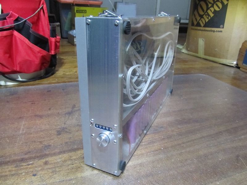
Almost complete!
The outer side.
All that is left is overload/overdischarge protection for the battery pack. It is alread

useable in this state.
http://quan-diy.com/projects/apower/powerbank2.htm
هناك تعليق واحد:
Great post! I really like the simple DIY approach and how it shows that portable energy solutions can be built with basic components and creativity. A solar power bank is a smart idea for outdoor use, but real efficiency always depends on proper design, battery management, and panel quality. Understanding these fundamentals is also very important when working on professional PV plan sets, where system accuracy and energy optimization matter the most. At PTOEdge, we appreciate practical renewable energy content like this that encourages hands-on learning and smarter solar solutions.
إرسال تعليق