
Make your own Solar Mobile Charger
A solar panel converts solar energy into electrical energy. Solar mobile charger regulates this electrical energy such that it could be used to charge mobile phones. Read this article to know how to make a solar mobile charger at home.
Solar mobile charger
Solar mobile charger is a device which can charge mobile phones using solar radiation. Its major component is a compact solar panel. This solar panel traps solar energy and produces an output voltage. But, since the light radiations falling on the solar panel can vary, the output voltage becomes unstable. For charging a mobile phone, stable voltage is required. So, to make the output voltage stable and regulated, we use a voltage regulator circuit along with the solar panel.
Most of the mobile phones have computer connectivity via USB cable. USB port establishes 4 connection terminals. The connection terminals at the two extreme ends are the supply terminals. In a female USB connector (port via which we plug in USB devices to computer), these terminals carry 5V DC. When a mobile phone is connected to the USB port of a computer, it utilizes this 5V supply to recharge battery. This feature is used in a solar mobile charger. It converts and regulates solar energy to 5V DC and the output will be available through the female USB connector. To this connector, we can easily connect a mobile phone via data cable.
Materials required
2)Voltage regulator IC 7805
3) 100uF, 25V capacitor
4) 10uF, 25V capacitor
5) 100nF capacitor
6) USB female connector
7) PCB
8) Connecting wires
9) Soldering accessories
Let's start building
Solar panel
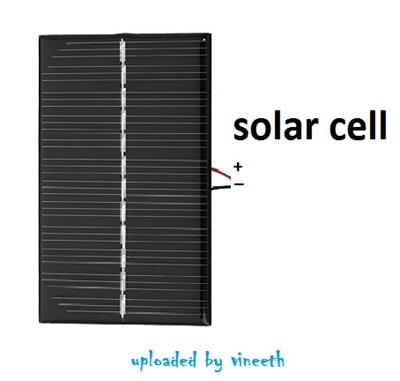
First of all, take the solar panel. On its back side, we can see two connecting wires. One is in red colour and the other is in black. The red wire is the positive terminal and the black wire is the negative terminal. There is nothing much to do with the solar panel.
Voltage regulator
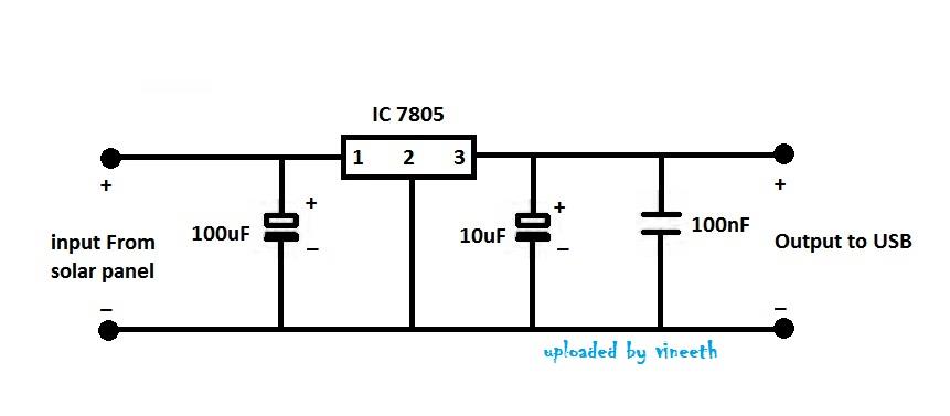
The regulator circuit consists of the following components.
1) IC7805
2) 100uF
3) 10uF
4) 100nF
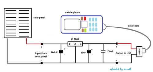
Circuit diagram
Regulator on PCB
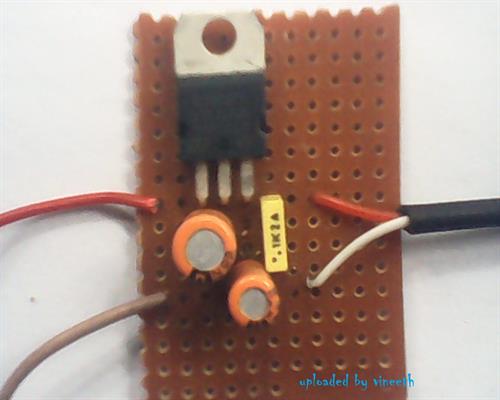
Solder all the components on a PCB as shown in the circuit diagram. To test the regulator circuit, connect voltage between 8 V and 18V to the input of voltage regulator. Now, measure the output. The output should be constant and it can be any value between 4.75 V and 5.25V. If so, your circuit is working properly.
Next, we need to connect it to the USB port. This has to be done carefully
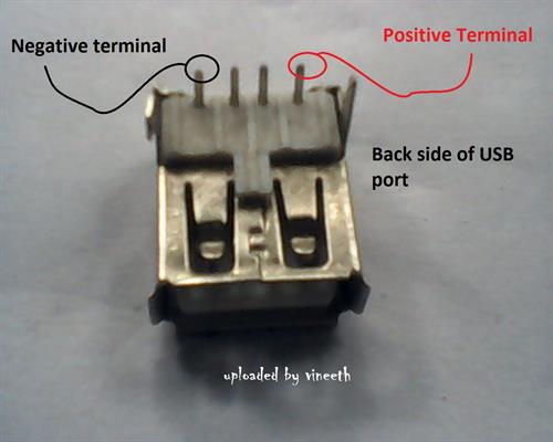
Solder the positive output wire of the voltage regulator to the USB's positive. Similarly, connect the negative output of regulator to the negative of USB. The USB port must be fixed properly to the PCB. Next, connect the solar panel to the input of the voltage regulator (positive of solar panel to positive input of voltage regulator and negative of solar panel to negative input). Once everything is connected, measure the output voltage in open sun light. It should be around 5V. Now, connect your mobile phone and you will see it charging.
Once everything is done, fix the circuit properly on a plastic box. The solar panel should face the Sun
http://www.techulator.com/resources/10562-Make-your-own-Solar-mobile-charger.aspx
ليست هناك تعليقات:
إرسال تعليق