
Sun Jar Prototyping
Sun jars are solar-powered LED night lights. You can find them for sale all over the web and even at some brick-and-mortar retail stores. Making one looked like a fun project, so I started Googling and checking the normal places like Instructables for project ideas. Surprisingly, all the DIY sun jar guides I could find centered around hacking up a pre-built solar garden light and stuffing the guts into a jar.
That didn’t sound like any fun to me. This had to be a really simple circuit. Why not build it from scratch and learn something along the way? I decided that would be my project.
Designing the circuit
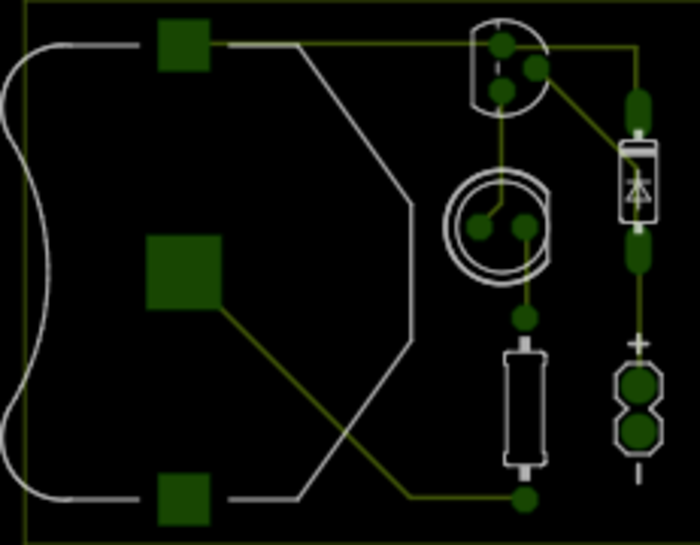
My first step was reading about battery-charging circuits. I wanted this to be a simple project, and I knew I’d be working with a low current from a solar panel, so trickle-charging seemed like the best option. After Googling around for a bit, I settled on this circuit configuration:

Click on the circuit image above to visit the CircuitLab page and read a full explanation of how it works.
Building the circuit
The next step was to start spec’ing out the parts. Most LEDs have a forward voltage — also called a voltage drop — of around 2V, with some blues dropping as much as 3.8V. This meant I needed a battery of 3V or more. A normal AA or AAA cell is about 1.2V, and I had some rechargeables around, so I strung 3 AAAs in series and made myself a 3.6V battery pack.
To trickle charge a 3.6V battery I needed a solar panel that could produce a higher voltage than that and also would fit in the lid of a jar. After a lot of searching I found these inexpensive 5V solar “badges” from Adafruit.
Next, I built the circuit on a breadboard to test it out. Here’s a video of me demonstrating the light turning on when the solar panel gets dark:
I could tell right away that the battery would light the LED and voltage from the solar panel would control the transistor, but it took some time to test charging the battery. I observed with a multimeter that the battery voltage was higher after several hours in the sun, but I also left the breadboard in a sunny window for a couple of weeks as a real test, and the LED kept lighting up every night.
Fitting it in a jar
Now that I’d demonstrated that the circuit worked, the next step was to build a prototype. The 3AAA battery pack was too big to fit in a jar, so I went searching for a better battery. I found these cool 3.6V rechargeable lithium ion coin cells
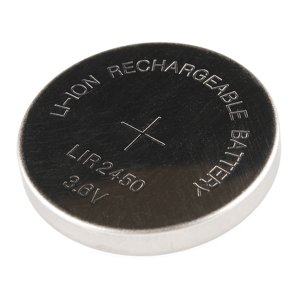
at Sparkfun which ended up being perfect, so I ordered several of them along with some matching holders.
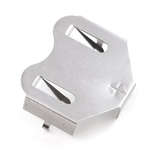
Here’s where ordering stuff online can bite you. I didn’t realize until they arrived that the holders are only the positive contact for the battery. They’re intended for use on a PCB where a solder pad on the board provides the negative contact. Bummer! So I had to wait a few more days for some breakout boards to arrive.
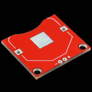
Once I received the breakout boards, I soldered one up and used it to replace the 3AAA battery pack in my window circuit. I let that run for several more weeks as a battery test.
Lithium ion batteries are really sensitive to overcharging, and you can easily ruin them that way. Most LI-charging circuits employ circuitry to cut off the charger once the battery has reached a certain float voltage. I didn’t think too much overcharging would happen in my circuit, so I decided to gamble $3 and find out what would happen. So far everything seems to work fine. The LED lights up brightly after sunny days and runs for several hours. On overcast days it’s somewhat dimmer and doesn’t last as long. I haven’t measured a battery voltage above the 3.6V rating, so I don’t think it’s overcharging. I guess it could be different in areas that get more intense direct sunlight for longer periods of time.
Making the first real prototype
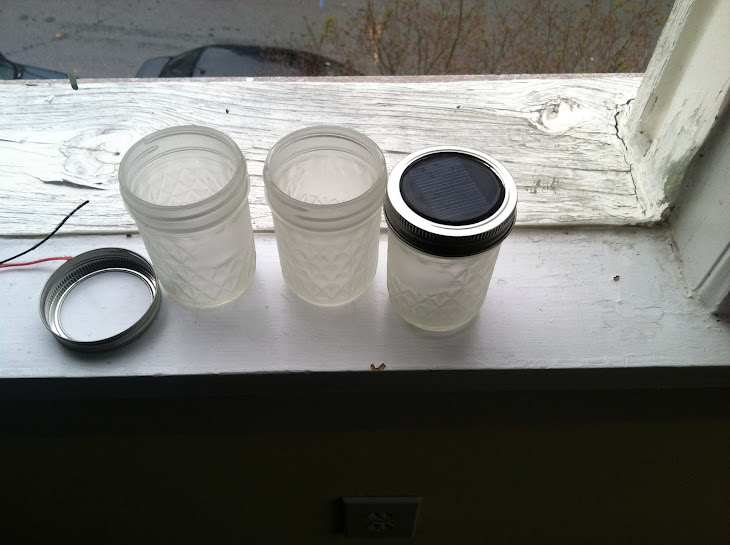
With a working circuit and a smaller battery I next built the actual prototype sun jar. Most commercial sun jars put the solar panel underneath a hinged glass lid. Since I had weatherproof solar panels that could go on the outside of a jar, I decided to go for a slightly different look, and I ordered these 8-ounce Ball Jars from Amazon.

I also picked up some frosted glass spray.
I soldered a couple of wires to the solder pads on the back of the solar panel and drilled a hole in the jar lid. I routed the wires through the hole and then adhered the panel to the lid with some RTV Silicone sealant.
This stuff takes patience because you have to clamp it overnight, but it makes a good weatherproof seal, so the finished jar can be left outside.
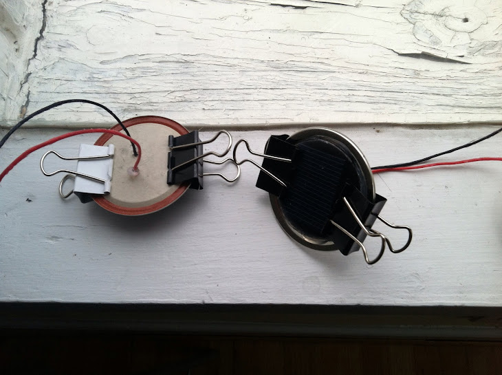
I took the other circuit components off the breadboard and soldered them down to a little piece of protobard. Once the silicone had cured on the lid I wired the solar panel to the rest of the board.
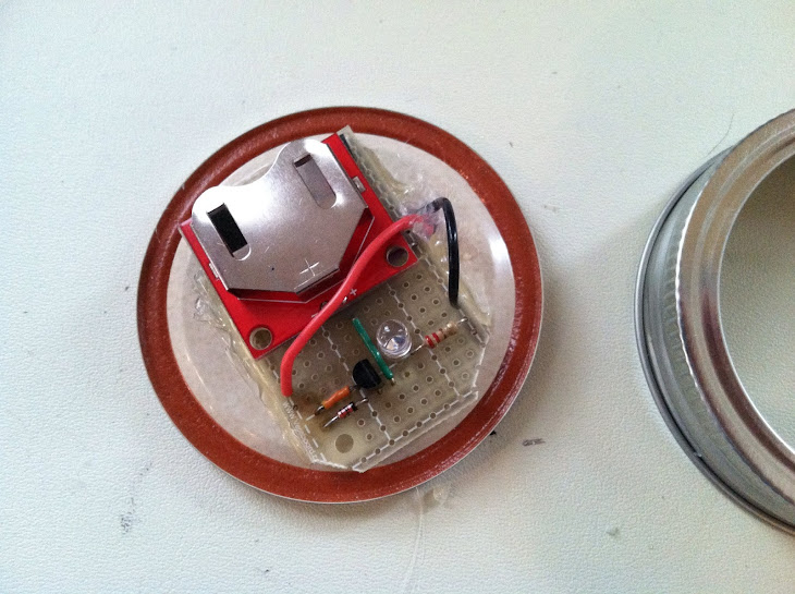
Adhering the board to the underside of the jar lid proved pretty tricky. I couldn’t get silicone to hold, so I went to hot glue. It seemed to work at first, but then popped apart a couple of hours later. These jars are made for food, and it turns out the non-stick stuff they coat the underside of the lid with is pretty damn non-stick. The third time was the charm, though. Gorilla glue held really well.
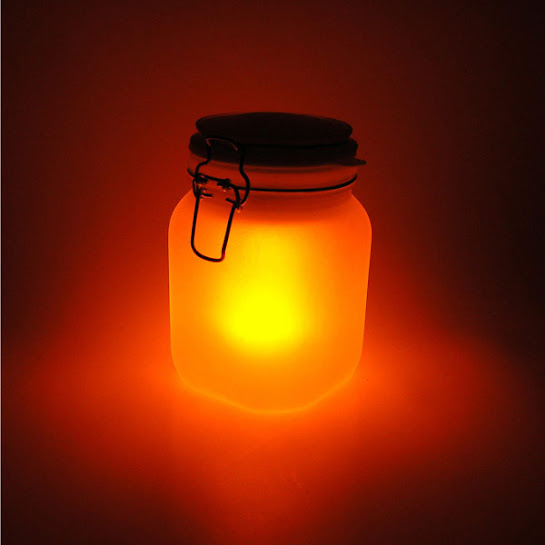
The jars actually look pretty nice after being frosted with the spray. Here’s one complete jar and a couple I’m still working on.
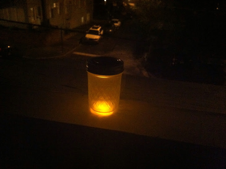
Here’s how the first completed jar looks in the dark. Pretty good if I do say so myself.
Designing a custom PCB
Building the sun jar was really fun, and I want to make a lot more with different size jars and different color LEDs, so it would be really nice to get this circuit on a PCB. That way I could just drop in the parts and solder, rather than buying more battery breakout boards and cobbling everything together on protobard.
First I downloaded Eagle. It seemed to be the DIY community standard and Sparkfun has open source Eagle libraries that include the battery holder wanted to use.
I used these two really great tutorials, also by Sparkfun, to first create the circuit schematic and then the PCB layout.
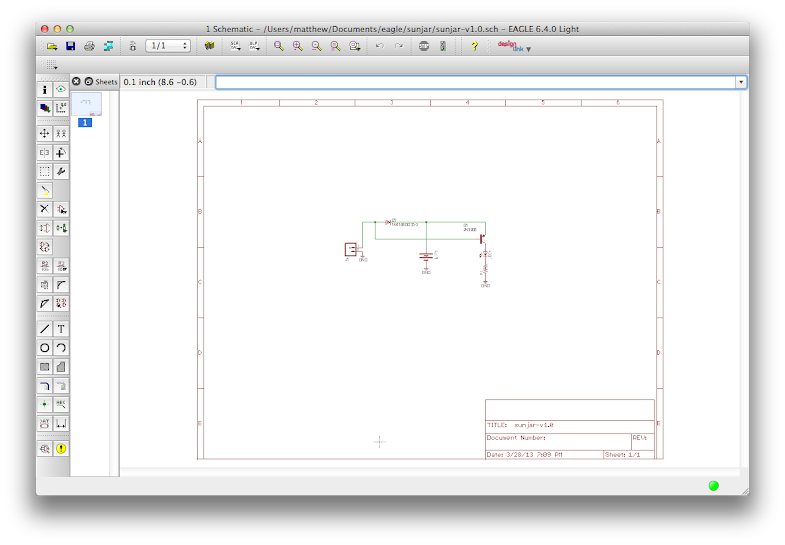
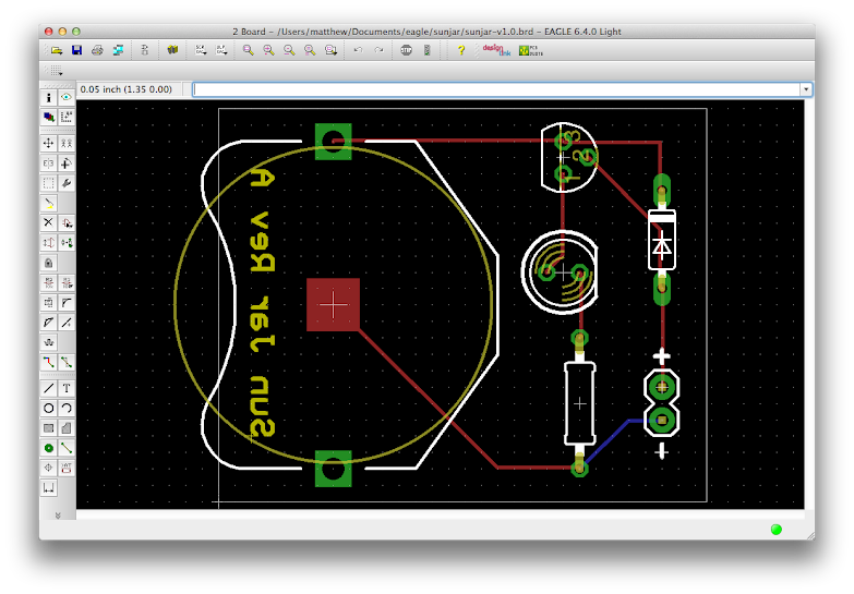
If you’d like to play with this design, you can fork it on Github.
The tutorials were really great and comprehensive. I didn’t have to do much Googling outside of them to figure things out. The only real issues were that the Windows-oriented keyboard shortcuts didn’t work for me on OS X, so I had to dig through the menus for a couple of things, but it wasn’t too bad.
Fabricating the PCB
With the layouts done and Gerber files generated, I needed a place to get the PCB printed. Adafruit has some good reviews and recommendations for board houses, but even the cheapest of those charge a $35 setup fee and it looked like I might have to spend time on the phone to get the order done.
Just when I started to feel discouraged, Sparkfun came to the rescue again with their brilliant BatchPCB service. You simply upload a zip of your Gerber files and it does some quick checks to verify the files. Once they clear, your board shows up on the Marketplace view where you can order it. The set up fee is only $10, so I’ve ordered a prototype of my board for under $20 including shipping.
It’ll take a few weeks for the first board to get to me, but if it works, I’ll post an update here in case anyone wants to buy one. I think this might also make a fun “learn to solder” kit since it only has a few parts and they’re all of the through-hole type. If you’d be interested in buying a kit of these parts including a PCB, please leave a comment here or let me know at matt.manning@gmail.com.
http://mwmanning.com/2013/03/31/Sun-Jar-Prototyping.html
ليست هناك تعليقات:
إرسال تعليق