الاثنين، 29 فبراير 2016

برامج المحاكات والتصميم في الطاقه الشمسيه Simulation

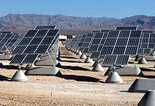
بالنسبه لتعلم Simulation في الطاقه الشمسيه

1- برنامج PVsyst دي من افضل برامج Simulation في الطاقه الشمسيه بيعمل محاكاه لاحمال AC واحمال DC والمضخات
البرنامج بتديله بيانات الموقع بتاعك والخلايا اللي بتستخدمها وغيرها .. وبيديك الخرج عباره عن تقرير كامل شامل الحسابات الفلكيه لشده الاشعاع والانتاج السنوي للتصميم وعدد module للخلايا وطرق توصيلها وغيره من الحسابات حسب النظام
برنامج PVsyst ليه نسخه Demo تقدر تحملها وتشتغل عليها وانت في البيت
2- برنامج SAM ودا برنامج ممتاز بيعمل Simulation لحاجات كتير من ضمنها الاحمال وانظمه الطاقه الشمسيه الحراريه والسخانات الشمسيه وطاقه الرياح و Biomass
برنامج SAM بتديله الدخل عباره عن بيانات الموقع والخلايا وغيره حسب النظام وبيديك الخرج علي شكل رسومات للقدره الخارجه والحسابات الفلكيه لشده الاشعاع السنوي وغيره
برنامج SAM ليه نسخه Demo تقدر تحملها وتشتغل عليها في البيت
3- برنامج PVsol من اقوي البرمج اللي بتعمل حسابات Shading في الطاقه الشمسيه للتصميم بتعرف من خلاله ازاي تظبط حسابات التظليل والمسافات اللي هتسيبها بين الخلايا حسب المكان والارتفاعات اللي جمبه وغيره
برنامج PVsol ليه نسخه Demo تقدر تحملها وتشتغل عليها وانت في البيت
http://www.valentin-software.com/…/photovo…/57/pvsol-premium
4- برنامج Sketch up +Archelios برنامج Sketch up بتقدر من خلاله ترسم البيت وابعاده وتجيب الخلايا من Archelios وتسقطها علي البيت وتشوف الخرج بتاعك وشكل البيت لما هيشتغل بالطاقه الشمسيه
البرنامجين تقدر تحملهم وتشتغل عليهم من البيت
5- برنامج TRNSYS من البرامج المييزه في الطاقه الشمسيه واللي بتعمل Simulation لا نظمه تسخين المياه بالطاقه الشمسيه وتشوف العمليه كامله علي البرنامج
برنامج TRNSYS ليه نسخه Demo تقدر تحملها وتشتغل عليها وانت في البيت
6- برنامج MATLAB من البرامج اللي بتعمل Simulation للخلايا الشمسيه وبيوضح شكل power وشكل الفولت والامبير و IV-curve
برنامج MATLAB تقدر تحمله وتشتغل عليه من البيت
----------------
Mohamed Abdallah

للمزيد اظغط على الصورة ادناه 


Solar PV panel model simulation in Matlab Simulink

A detailed modeling of photovoltaic module using MATLAB

Modélisation de Panneaux Solaires et Raccordement au Réseau Electrique

Modélisation de Panneaux Solaires et Raccordement au Réseau Electrique


La technologie photovoltaïque est régulièrement présentée comme une source viable d’énergie renouvelable. Relever les défis liés au développement et l’implémentation de ces systèmes requiert des outils de simulation capables de modéliser et d’analyser le comportement des différents composants électroniques. Ces outils doivent aussi permettre de modéliser les lois de commande associées, dans le but d’évaluer les performances du système complet.
Au cours de ce webinar, un ingénieur MathWorks va montrer comment utiliser des modèles dynamiques pour tester et valider les performances de systèmes photovoltaïques complets (des cellules photovoltaïques à la connexion au réseau, en passant par les convertisseurs DC-DC et DC-AC, et sous différents scénarii de charge). Les exemples utilisés démontrent comment la simulation permet de trouver le meilleur compromis lors des phases de conception, et permet aussi de développer et tester les lois de commande (par exemple, un algorithme Maximum PowerPoint Tracking (MPPT)).
Points forts:
  • Modélisation de composants électriques / électroniques (cellules photovoltaïques, convertisseurs, …)
  • Conception de lois de commande pour de l’électronique de puissance (régulation en tension et courant, Maximum Power Point Tracking (MPPT))
  • Connexion au réseau électrique (analyse transitoire, harmonique, gestion de la puissance réactive)
Presenter: Laurent Vaylet

http://fr.mathworks.com/videos/modeling-solar-panels-and-their-integration-with-grid-power-82133.html

Caractérisation et Simulation d’un Panneau Solaire Simulink


Caractérisation et Simulation d’un Panneau Solaire

Lors de cette vidéo, vous découvrirez les différentes techniques de modélisation d’une cellule photovoltaïque. Vous verrez ensuite comment la simulation d’un modèle physique permet de caractériser le panneau solaire.
Pour modéliser un système photovoltaïque comprenant le panneau solaire, l’électronique de puissance de conversion ainsi que les charges, voir le webinar  

الأحد، 28 فبراير 2016

Solar PV tracker

Picture of Solar PV tracker
For a class project (PV Design, Appalachian State, Dr. Dennis Scanlin) I decided to try making a low cost PV (photovoltaic) tracker. Being able to follow the sun's path through the sky can raise your solar panel system's output considerably (30-50%), but the argon filled ones can be a bit pricey, and seem to be a bit unsteady in wind. I looked at several different designs, looked at what materials I could find, and this is how I did it.

The panel is mounted to a frame, which is attached to two bike wheels. The wheels are mounted to a larger wooden frame, and the wheels and panel are moved by a 12 volt linear actuator. The sensor is an LED model and is purchased from Redrok Energy.

The LED sensor senses the path of the sun and tells the actuator how much to move to keep the panel properly oriented. At the front of the tracker are two legs that can be adjusted to the proper altitude for seasonal changes.

I used bicycle wheels because they are durable, strong enough to handle some weight, and best of all, in my case, free!

Step 1: What do you need?

Picture of What do you need?
Here is what I used to make this tracker, and where obtained:

*Several treated 2x4's (Lowes)
*Two wheels from a free bicycle- free or almost free bikes are pretty easy to find from the local landfill or thrift store
*A piece angle iron with pre-punched holes (Lowes)
*A 12 volt linear actuator-(~$75?)- (Ebay)
*An LED tracking sensor- (~$40)(http://www.redrok.com/led3xassm.htm#led3xforsale )
*Various nuts, bolts, screws, cable and wire -(scrounging around my workshop)

Step 2: Making the base, and mounting the wheels

Picture of Making the base, and mounting the wheels
solar project 002.jpg
To make a nice, sturdy base I cut the 2x4's at angles and put them together to make two triangles. You can make them whatever size you need, depending on the size of your panels. I then tied them together with a couple of 2x4's at the base, and a couple up top. This made a nice, sturdy base to mount the wheels to.

I cut a couple of small pieces of angle iron with a hacksaw, found the mid point on the cross members, and attached them exterior woodscrews. I put the wheels through the holes, and spun them with satisfaction.

Here is a picture of the top wheel being mounted.

Step 3: Adding the wooden frame to the wheels

Picture of Adding the wooden frame to the wheels
I then mounted the 2x6 piece to the bike wheels by drilling holes through the bike rims and the 2 x 6 and bolting them together. I also used big U-bolts to clamp the rims to the board by drilling holes through the board and clamping it down tight. The board pivoted nicely on the two bike rims.

The 2 x 6 isn't wide enough to mount the panel to, so I added some smaller 2 x 4's to the top and bottom of the board, cut to the size of the panel. Each 2 x 4 board is as long as the solar panel is wide, and was attached to each end of the 2 x 6 with screws and bolts.

This allows a nice flat place on which to mount the panel. I attached small pieces of angle iron to the holes on the end of each panel, and then screwed them to the wooden frame. This secured the panel to the frame.

Step 4: Adding the linear actuator

Picture of Adding the linear actuator
solar tracker 014.jpg
I purchased the 12 volt linear actuator on Ebay. It's built to hold up in the weather, is strong enough to move however many panels I would want to add to it, and has a long enough stroke to move the panels all the way from one side to another. (I think the stroke is 8", but I'd have to double check.)

I mounted it on the one side of the frame with a through bolt, and attached it to the movable solar panel frame. To mount it to the side of the frame holding the solar panel I just used a staple on the board that moves on the bicycle wheels. A short piece of cable goes through the hole on the linear actuator and the staple, and iIused a small cable clamp to secure it. This allows everything to move around and flex as needed when it's moving. When hooked to the battery the actuator moves the panel all the way to one side, and reversing it moves it all the way back.

The next step is giving the tracker the smarts to know when and how much to move.

Step 5: Adding the LED tracker

Picture of Adding the LED tracker
P1010151.JPG
I wish I had more pictures of the LED tracking unit, but there is plenty of info at Redroks website. The unit uses LED's to measure the position of the sun and tells the linear actuator how much to move and where to position the panel. It's really a slick little unit, and at a great price.

Go to http://www.redrok.com/led3xassm.htm#led3xforsale to purchase one if you want to try this yourself. There are plenty of pictures of how other folks have mounted them at http://www.redrok.com/electron.htm#led3x . I put mine in an empty peanut butter jar and mounted it to a 2 x 4. I attached the 2 x 4 to the side of the unit to get the LED tracker up above the panel to give it an unobstructed view of the sun. 

Step 6: Finishing it up

Picture of Finishing it up
solar tracker 022.jpg
This is pretty much the finished product, and it works well. I had an issue of condensation accumulating inside the peanut butter jar and had to seal it better. The size of the tracker can be made to fit however many panels you need, and there are many ways to configure a tracker like this. I hope this was a helpful, and good luck in your tracker project!

-------------------------
http://www.instructables.com/id/Solar-PV-tracker/

Installation électrique sous baguette PVC

Installation d’un projecteur à détecteur de mouvement

Installation de spots de plafond encastrables

Installation d'un tableau électrique pré-équipé

Installation d'un néon d'atelier

Installation d'un va-et-vient (montage théorique)

Comment commander trois lampes avec interrupteur va et vient 1 canal

DIY homemade solar generator

How to wire a Portable Solar Generator

DIY Portable Solar Power Generator

This DIY 110 amp hour portable generator is designed to be powered by a 100W solar panel and 2 55AH AGM sealed batteries. The system includes a 30A PWM solar charge controller and a 400W pure sine wave inverter. 12V, 12V USB, and 110V AC outlets offer flexibility for powering/charging a variety of appliances. The system is also set up to be trickle charged via a SAE 2-pin port that allows for a convenient connection to an AC float charger. Total cost of all materials required to build this project, including all components of the generator and the solar panel, was approximately $950 USD.


Part 2


WIRING SCHEMATIC
PARTS LIST

différentiel

Ce guide pratique présente chaque étape nécessaire au rebobinage d'un mo...

Démontage remontage moteur électrique

Fonctionnement du disjoncteur différentiel

Comment repérer le fil neutre dans une prise ? Leroy Merlin

Comment utiliser un multimètre ?

Comment installer un 2ème tableau électrique ?

Localiser la source d'une panne électrique sur votre disjoncteur

Localiser la source d'une panne électrique sur votre disjoncteur

Comment monter un coffret électrique ?

Comment installer un interrupteur différentiel ?

Le Disjoncteur Présentation Rapide

اصنعها :اللوحات الشمسية المستوية

اللوحات الشمسية المستوية
00
سنقوم بوصف صناعة لوحة شمسية مجهزة بـ 36 خلية شمسية من أجل توليد تيار كهربائي بجهد 18 فولط.

تقديم
لقد كان مشروعا سهلاً ويمكنك القيام بهلقد إشتريت خلايا شمسية مقاس 3×6 بوصة وسوف نحتاج إلى 36 خلية شمسية موصلة على التوالي لعمل اللوح الشمسيكلخلية تنتج حوالي 0.5 فولط وعند استخدام 36 خلية على التواليسيكون المجموع 18 فولط وو فرق جهد كافي لشحن بطاريات 12 فولطهذا النوع من الخلايا الشمسية نحيف جدا كالورق وهش كالزجاج ومن الممكن أن يتأذى بسهولة.
هناك عدة أحجام من الخلايا الشمسية غير 3×6 بوصة، يمكنك استخدام خلايا أكبر أو أصغر، فقط ضع في الحسبان بضعة أشياء وهي:
  • الخلايا من نفس النوع تنتج فرق جهد متساوي بغض النظر عن حجمها، لذلك عدد الخلايا هو المهم في هذه الحالة.
  • الخلايا كبيرة الحجم تنتج تيارا أكبر، والصغيرة تنتج تيارا أقل.
  • مجموع الطاقة الناتج من اللوح الشمسي التيار × فرق الجهد.
لذلك فإن استخدام خلايا حجمها أكبر سـيعطي طاقة أكثر ولكن سيصبح اللوح أكبر وأكثر وزناأما استخدام خلايا صغيرة فـسيضمن لك بناء لوح صغير الحجم وخفيف الوزن، ولكنفي المقابل لن ينتج طاقة كبيرةوأيضا خلط أحجام مختلفة ليست فكرة جيدة لأن التيار الناتج سيكون مرتبطا بأصغر خلية ولن تعمل الخلايا الكبيرة بكامل كفاءتها.

الخلايا التي أستخدمها حجمها 3×6 بوصة وتنتج تقريبا أمبير، وسوف أقوم بتوصيل 36خلية على التوالي لأحصل على فرق جهد أكثر بقليل من 18 فولطومن المفترض أن يكون اللوح قادرا على إنتاج طاقة مقدارها 60 واط في وضح النهار، والتي يمكن توصيلها ببطارية لـيتم تخزين الطاقة فيها واستخدامها ليلا بالإضافة إلى استخدامها نهارا.
بعد أن تشترى الخلايا الشمسية ضعها في مكان آمن حتى لا تنكسر أو يلعب بها الأطفال حتى تكون مستعدا لتركيبها في اللوح.


تحضير اللوح الخشبي
اللوح الشمسي دائما ما يكون مسطحا جدالذلك، بدأت ببناء صندوق مسطح وقد جعلت الزوايا مسطحة حتى لا تحجب الشمس عن الخلايا الشمسية وقمت بتقسيم اللوح إلى نصفين، كل نصف سيحتوي على 18 خلية شمسية حتى يكون أسهل في التركيب.
هـذا رسم تخطيطي يوضح أبعاد اللوح الشمسي وهو منقسم إلى نصفين،

تـوجد بُروز على الحواف:
إرتفاعها 3/4 بوصة وعرضها 3/4 بوصة وجميع الأبعاد بالرسم مُقاسة بالبوصة.

وبالطبع يمكنك عمل أي تصميم آخر مناسب.
03
وهذه صور للوح الخشبي الذي سأقوم بتركيب الخلايا الشمسية عليه، وكل نصف سيحتوي على 18 خلية شمسية، ولاحظ الثقوب الصغيرة بالحواف والتي قمت بصنعها لكي يكون الضغط داخل اللوح مساوٍ للضغط الخارجي حتى لا يؤثر على كفاءة الخلايا الشمسية وجعل الرطوبة تخرج من اللوح.

يجب أن تكون هذه الثقوب في قاع اللوح وإلا ستسقط عليها الأمطار، ويجب أن يكون هناك أيضا فتحات في الفاصل الخشبي الذي يقسم اللوح إلى نصفين ويفضل أن تكون المسافة الفاصلة بين كل ثقب هي ربع بوصة.
04
05
بعد ذلك قمت بقطع لوحين من الخشب المُسطر بالثقوب ووضعهما داخل اللوح الشمسي حتى تكون قاعدة للخلايا الشمسية، وهذه خطوة غير مهمة ولكني قمت بها لأن هذه الألواح متوفرة ليس أكثر.
06
حتى أحمي الخلايا الشمسية من تأثيرات الطقس قمت بتغطية اللوح بالزجاج الصناعي وهو يكاد يكون بلاستيكي وخفيف الوزن وغير هش كالزجاج العادي ويفضل استخدامه، انظر للصورة التالية.
07
هنا قمت بثقب ألواح الزجاج الصناعي حتى أقوم بتثبيتها على اللوح الخشبي بواسطة المسامير القلاووظ حتى أستطيع فكها متى أردتلكن، إحذر وأنت تثقب الزجاج الصناعي فمن الممكن أن ينكسر كما حدث معي.
08
قمت بطلاء اللوح الخشبي من الداخل والخارج بالدهان للحفاظ عليه من الرطوبةويمكنكاستخدام أي لون متاح لديك بيد أني فضلت اللون الأبيض.
09
قمت أيضا بصباغة الألواح المُسطرة بالثقوب باللون الأبيضولقد أكدنا من قبل أن استخدامها غير مهم بل هي لتسهيل وتركيب الخلايا ليس أكثر من ذلك، ويرجى التأكد منصباغتها جيدا حتى لا تتجعد من الرطوبة مما قد يؤدي إلى تخريب الخلايا فيما بعد.
10

تجهيز الخلايا الشمسية
إنتهينا الآن من تجهيز اللوح الخشبي وسنقوم بعدئذ بتجهيز الخلايا الشمسيةعندما تشتري الخلايا الشمسية ستأتي في الغالب ملصقة ببعضها البعض وبينها شمع أو تأتي منفردة وهو الأفضل.

إذا كانت ملتصقة فأفضل طريقة لفصلها هي الماء الساخنضعها في إناء به ماء على النار واتركها تسخن بالتدريج ولا تترك المياه تغلى أو تخرج فقاعات وحاول أن تخرجها قبل حدوثذلكوهذه أفضل طريقة استطعت الوصول إليها لفصل الخلايا الشمسية وأقوم بالتأكيد مرة أخرى أن الخلايا الشمسية المنفردة أفضل.
11
وهذه صورة أخرى توضح الأواني التي كنت أقوم فيها بفصل الخلايا عن بعضها البعضبسبب الشمع اللاصق بينها.
12
والصورة التالية تظهر شكل الخلايا بعد فصلها ووضعها على منشفةأنا شخصيا أفضل عدم فصلها قبل عمل اللوح الخشبي لأن تخزينها منفصلة قد يكون صعبا أحيانا.
13

تركيب الخلايا الشمسية
هنا قمت برسم مستطيلات بقلم الرصاص على الألواح المُسطرة بالثقوب أو حتى على اللوح الخشبي مباشرة إن لم تكن تستخدم الألواح المثقوبةهذه المستطيلات تحدد أماكن وضع الخلايا الشمسية على اللوح ومن ثم سأقوم بتوصيلها مع بعضها على التوالي وأوصل نصفي اللوح على التوالي أيضا.
14
لقد إستخدمت مكواة لحام قصدير لتوصيل الخلايا بعضها ببعض وكن حذرا ولا تضغط على الخلايا بقوة حتى لا تنكسر.
15
العديد من الأشخاصيسألونني عن كيفية التوصيل بالضبط، لذلك قمت بعمل الرسمجانبه للتوضيح، حيث أقوم بتوصيل السلك السالب والموجود فوق سطح الخلية بالسلك الموجب الموجود أسفل الخلية التالية لها.
وهكذا أكون قد وصلت الخلايا على التوالي.
16 
قمت بتكرار الحركة السابقة إلى أن تم لحام جميع الخلايا الشمسية فـحصلت على الشكل التالي:
17
في هذه المرحلة قمت بلصق الخلايا بواسطة السيليكون ووضعت قليلا منه وسط كلخلية ثم ألصقتها في مكانها الذي قمت بتحديده بقلم الرصاص من قبل.

كن حذرا وأنت تقوم بـهذهالعملية ولا تضع السيليكون في منطقتين بل اجعله في منطقة واحدة وهي وسطالخلية حتى لا تنكسر منجراء التغيرات الحاصلة لهاكما لا تكثر من السيليكونأيضاوهذا هو الشكل النهائي للوح:
18 
19
إستخدمت سلك نحاس للتوصيل بين الصف الأول والثاني من الخلايا، وهناك أيضا واحد آخر للتوصيل بين الصف الثاني والثالث.
20


اختبار اللوح الشمسي
نأتي الآن إلى اختبار النصف الأول من اللوحوجدت أنه يعمل والآن علي أن أصنع نصفا آخرا مطابقا له.
21
كل نصف قد تم وضعه في اللوح الخشبي ولقد استعملت مساميرا لتثبيتهما في اللوح مثل الفضية الموجودة بالصورة التالية.
22
تمر أسلاك توصيل النصفين ببعضهما البعض بالثقوب الموجودة بالفاصل الخشبي بمنتصف اللوح.
23
كل لوح شمسي يحتاج إلى صمام ثنائي حتى لا تفرغ الطاقة في الليل أو عندما توجد غيوم بالسماءولقد إستخدمت صماما ثنائيا له معدل تيار يساوى 3.3 أمبيركما قمت بتوصيل الصمام الثنائي مع الجزء الموجب من السلك النحاسي ووضعته داخل اللوح الشمسي.
24
لقد أنشأت ثقبا بمؤخرة اللوح كي أخرج منه الأسلاك، وقمت بعمل عقدة في السلك ومن ثم وضعت بعضا من السيليكون على الفتحة لتثبت.
25
ثم وضعت سيليكون مرة أخرى على الثقب من الخارج.
26
لقد قمت بتوصيل قابس له قطبية بطرف السلك الخارج من اللوح لتسهل عملية التوصيل،ومن الأفضل أن تكون وصلة أنثى لتقليل الخطر وليست وصلة ذكر كما بالصورة التالية.
27
أو تكون وصلة التالية مثلا:
28 
هذا هو الشكل النهائي للوح الشمسي وهو مغطى بالزجاج الصناعي وسوف أقوم بإختباره بعدئذ.
29 
قمت باختبار اللوح الشمسي في وضح النهار وكان الـجهد الكهربائي الناتج يساوي 18.88فولط وهو ما كنت أريده.
30 
قمت أيضا بقياس شدة التيار الكهربائي وكانت النتيجة 3.05 أمبيروهذا يعني أن اللوح الشمسي يعمل بكفاءة كما تم التخطيط له.
31 

المتانة
قمت بإضافة صفائح من الألمنيوم حول اللوح الشمسي لمزيد من القوة والمتانة.
32  

تأليف

تأليفMichael Davis
البريد الإليكتروني للمؤلفastronomermike@gmail.com
ترجمة بتصرفعبد الله سعد عبد الستار فراج (الجيزة – مصر)
البريد الإليكتروني للمترجمabdo.farrag@yahoo.com


المراجع


التعليقات

بحث هذه المدونة الإلكترونية